GCN Electromagnetic System
Concealed drive system, UCI-class bicycle
Concealed drive system, UCI-class bicycle
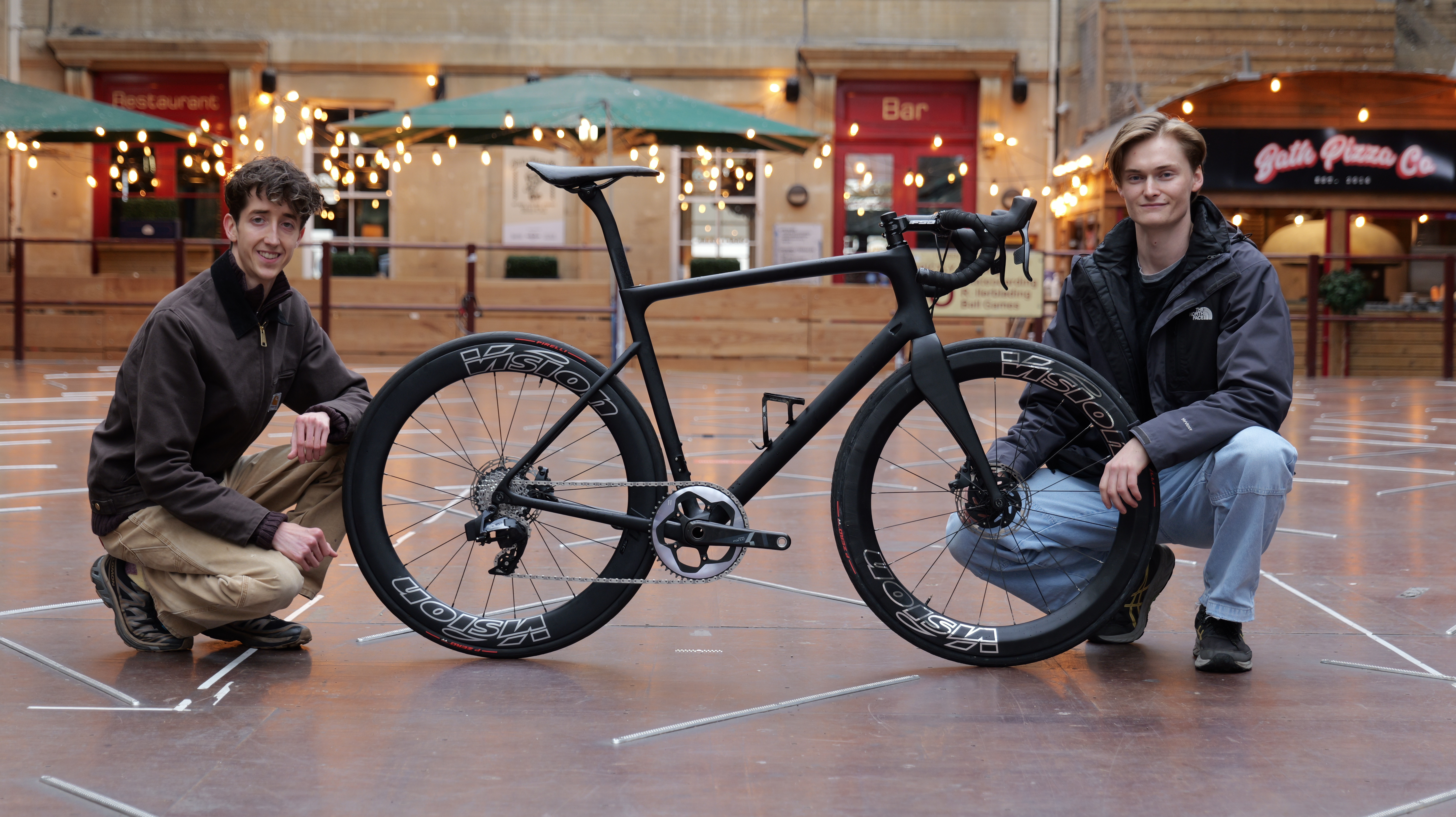
Motor doping, hiding electric motors inside racing bicycles, is the most immediate threat to competitive integrity in professional cycling. The first confirmed case was caught in 2016, the very first day the UCI introduced formal testing. Since then, compact motor and battery technology has only gotten smaller, more efficient, and easier to conceal. Yet detection still relies almost entirely on magnetic scanning by UCI-appointed commissaires operating under tight logistical constraints, with no independent oversight. The question isn't whether someone could cheat. It's whether the current system would catch them. This project set out to answer that, not to promote doping, but to expose exactly where the blind spots are. The approach borrows directly from ethical hacking in cybersecurity and adversarial testing in anti-doping science: build the attack to prove the defence needs to be stronger. Working independently with Global Cycling Network, I designed and built what is believed to be the first concealed electromagnetic drive system integrated into a UCI-class racing bicycle. The target was 20 watts, the gap between a 75th-percentile domestique and a 90th-percentile rider. Enough to change a race. The system was engineered to deliver that assist while remaining undetectable under most current UCI inspection methods. No institutional support. No workshop. £500 budget. Three months to a rideable prototype.
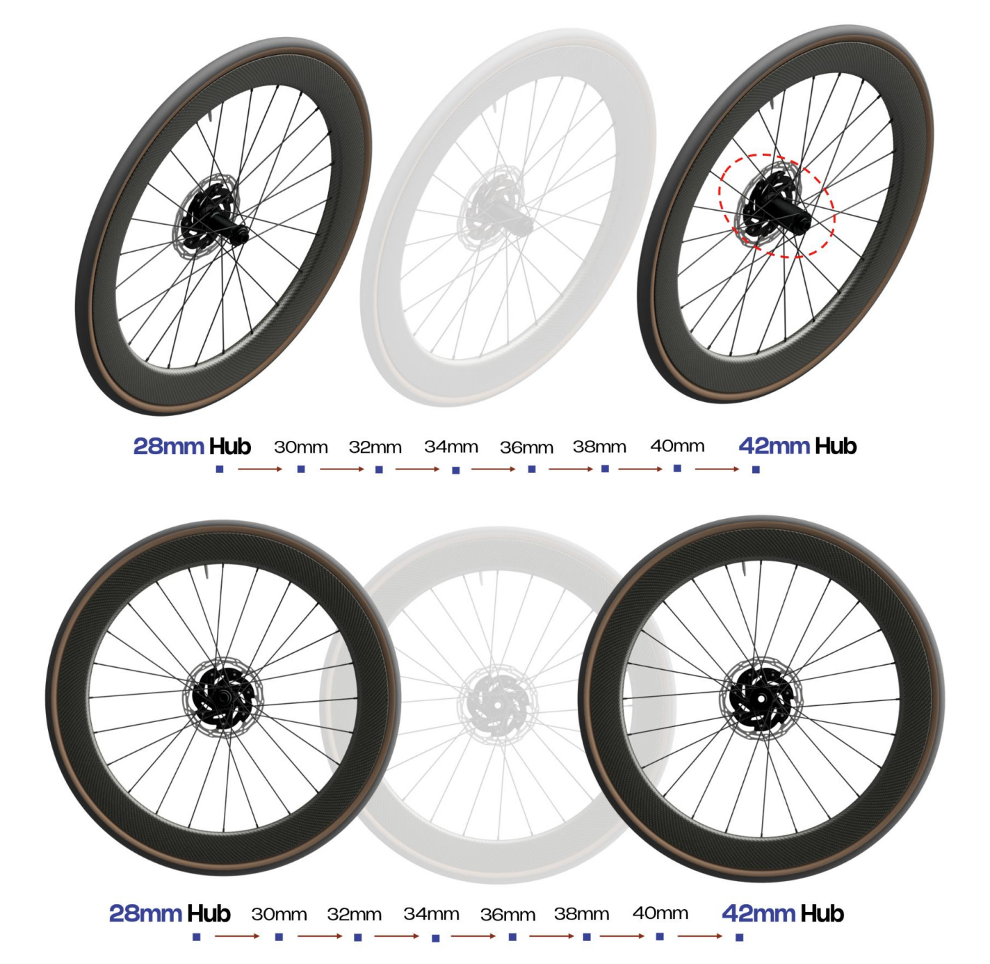
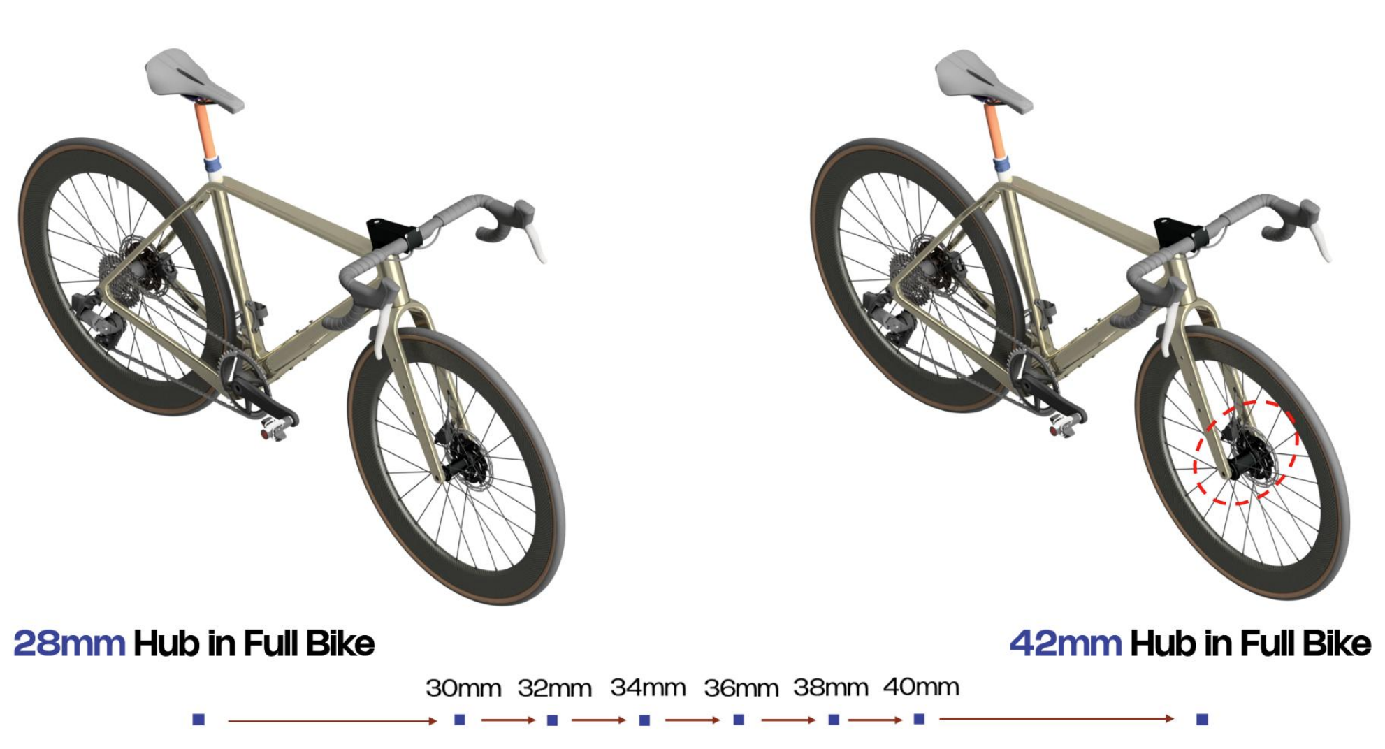
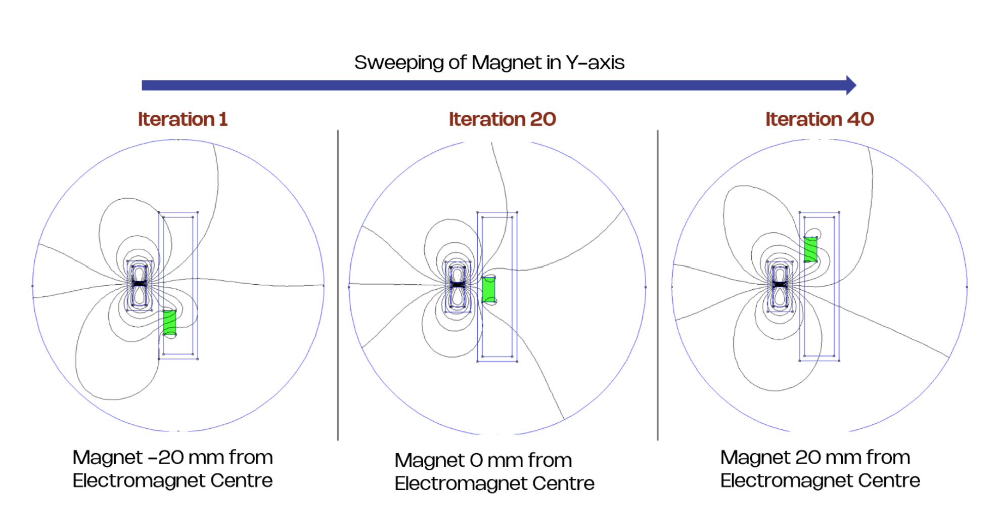
The instinctive approach was a miniaturised hub motor hidden in the front wheel, the approach used by every known motor doping system. But motor data showed that anything under 32mm diameter couldn't produce useful torque, and the stock hub was only 28mm. To find out how far it could grow before someone noticed, I ran a two-phase perception study with 20 participants: former competitive riders, professional team mechanics, and UCI officials. Each assessed CAD renders at 2mm increments from 28mm to 42mm, first as isolated wheels, then in full-bike context. Below 34mm, suspicion stayed under 10%. Above that, it spiked. A custom motor within that envelope would have required bespoke manufacturing far outside a £500 budget. The hub motor was closed out. The study gave the UCI a concrete detection threshold they didn't have before, and confirmed the electromagnetic architecture as the direction to pursue.
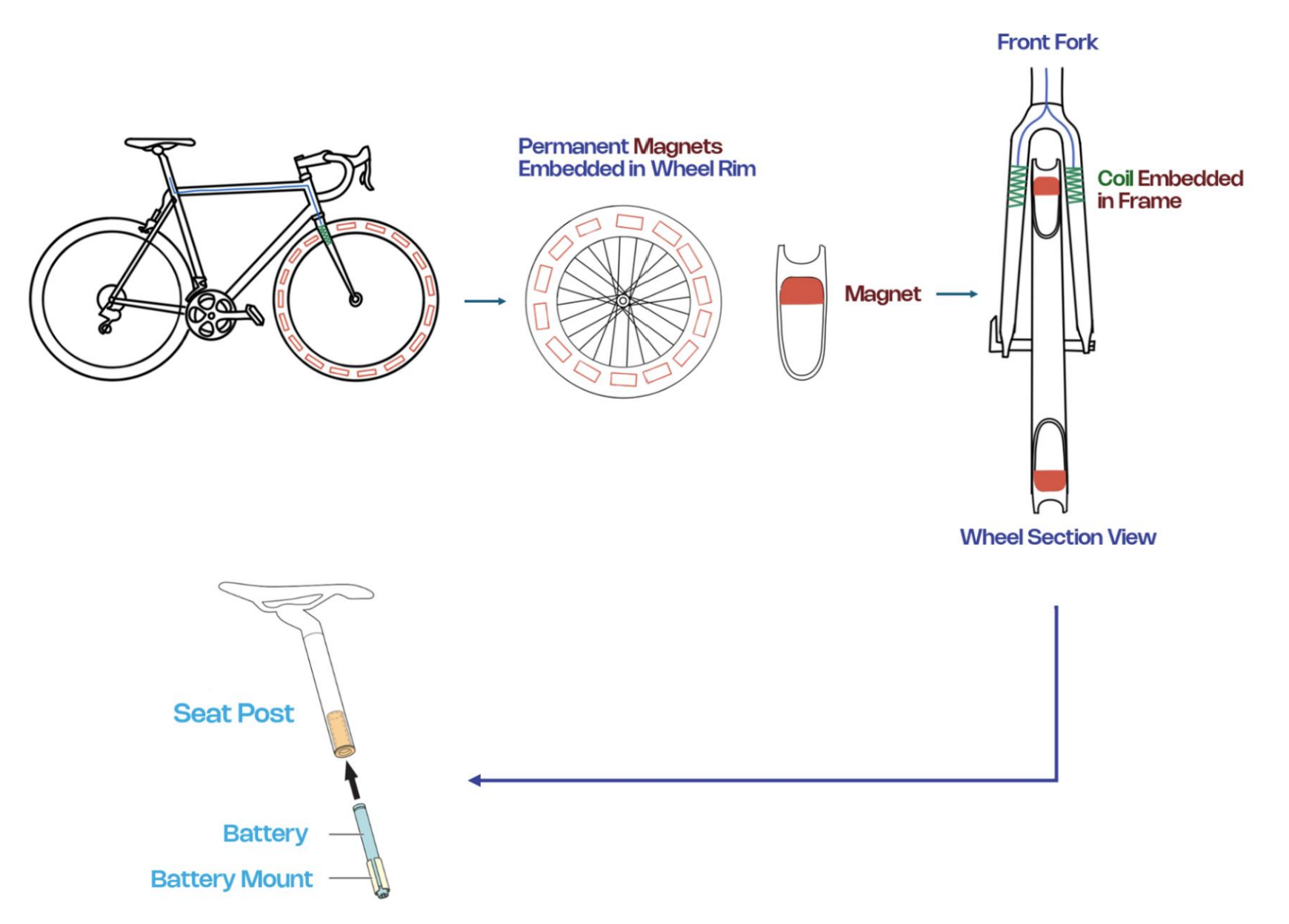
With the hub motor ruled out, the design pivoted to an electromagnetic rim-drive. Permanent N52 magnets embedded around the inner circumference of the wheel rim, with electromagnetic coils concealed inside the fork blades, two coils each on an individual motor driver firing simultaneously at approximately 4A per coil. A compact 4S lithium-ion battery hidden in the seat post completes the system, every component concealed within existing frame architecture. The front wheel was chosen deliberately: it can be swapped faster mid-race, and the core detection strategy relied on the magnetic wheel being introduced under cover of a staged puncture, avoiding pre- and post-race inspection entirely.
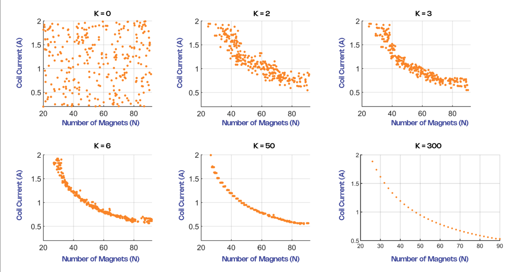
Each magnet-coil interaction was then modelled in FEMM, controlled via MATLAB. A single N52 magnet was swept across the electromagnet face in 41 steps, calculating tangential force at each position. This revealed a narrow effective drive zone of only 10 to 12mm around the coil centre, meaning control timing would be critical. That simulation fed a multi-objective genetic algorithm (NSGA-II) to explore the real trade-off: more magnets means more torque but more rotational mass on the rim, while more current means fewer magnets but more heat in a tiny enclosed fork housing. Population sweeps from 20 to 300 confirmed that larger populations produced smoother Pareto fronts, and convergence stabilised by generation 300. The algorithm converged on 48 N52 magnets at approximately 2mm air gap, balancing torque output, rotational mass penalty, thermal load, and battery runtime.
.jpeg)
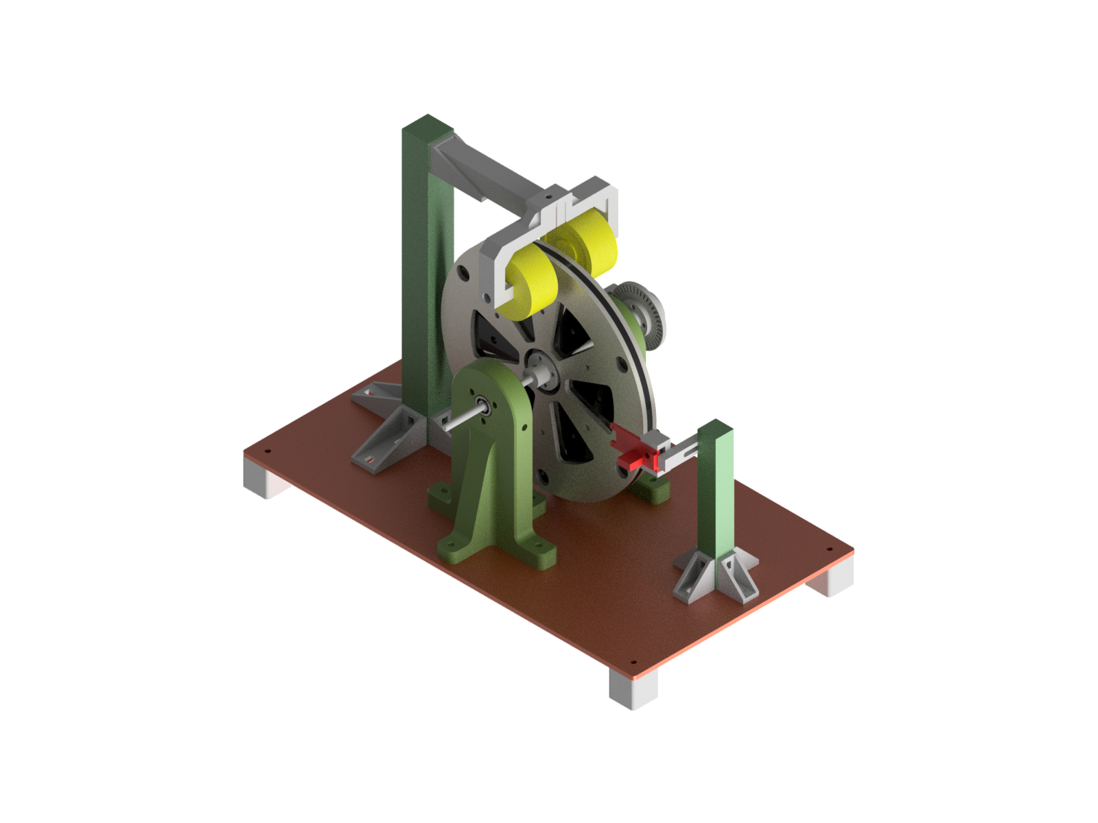
Before building anything into a carbon fibre racing bike, the control logic and magnet-coil interaction had to be proven at small scale. A 1:4 scale rim-drive prototype was designed to run at around 1,200 RPM, the equivalent rotational speed of a full-size bicycle wheel, with the geometry set up to test electromagnetic pulse timing under controlled, repeatable conditions.
The rig was built for modularity above all else. Electromagnet position, air gap, and the number of magnets on the rim could all be adjusted between tests. A central disc mounted on a 4mm stainless steel shaft carried the rim magnets, with 3D-printed bearing blocks and shaft couplings for stable rotation. A sliding Hall sensor mount allowed fine-tuning of detection angle and distance. At the rear, a photo-interrupt sensor and encoder disc provided speed feedback for later control iterations.
Control started simple: an Arduino polling an analogue Hall sensor, detecting magnet passes and firing a timed pulse through an L298N H-bridge to a 24V electromagnet. Timing was calibrated from the FEMM simulations, targeting a 4mm angular offset where peak attractive force occurs. It worked, but exposed real limitations. The standard Hall sensor could only detect north-facing poles, the system had no way to distinguish between consecutive magnets, and fixed timing delays drifted as RPM varied. A key physical finding was residual magnetic pull from the iron-core electromagnets: even when switched off, they introduced drag that interfered with free wheel rotation, a discrepancy between simulation and reality that motivated future exploration of air-core alternatives.
These limitations directly informed the shift to alternating magnet polarity with a latching Hall sensor, interrupt-based detection for higher timing precision, and ultimately the move to an ESP32-S3 with closed-loop PI current control in the final system. The prototype did exactly what it needed to: validated the physics, surfaced the problems, and gave us the confidence to commit to full-scale integration.
.jpeg)
.jpeg)
Early coil winding was done on a drill, and it was inaccurate enough that we built a custom winding rig using a NEMA stepper motor and Arduino with a motor controller, tensioning arm, and lead screw for horizontal wire positioning. This gave us precise control over speed, tension, and rotation, and critically let us test wire gauge and turn count as isolated variables against the same baseline. Four gauges were tested: 0.3mm, 0.75mm, 1.0mm, and 1.2mm, evaluated against response time, resistance, mass, and thermal behaviour. The 0.75mm gauge offered the best trade-off. Bobbin design went through multiple iterations: changes to diameter, core thickness, an iron washer inserted mid-print, air channels for cooling, aluminium heatsink cores, and different termination methods. The aluminium-finned core more than doubled run time at the same current compared to a plain PETG bobbin. A thermistor embedded in the coil was calibrated through a 20-point oil-bath resistance-temperature lookup table, then integrated into the control system as an overtemperature latch with hysteresis: firing disabled at 160°C, re-enabled when temperature dropped sufficiently. That live thermal data allowed current and duty cycle to be pushed closer to copper's 180°C material limit, gaining roughly 10% additional output on the 20W target.
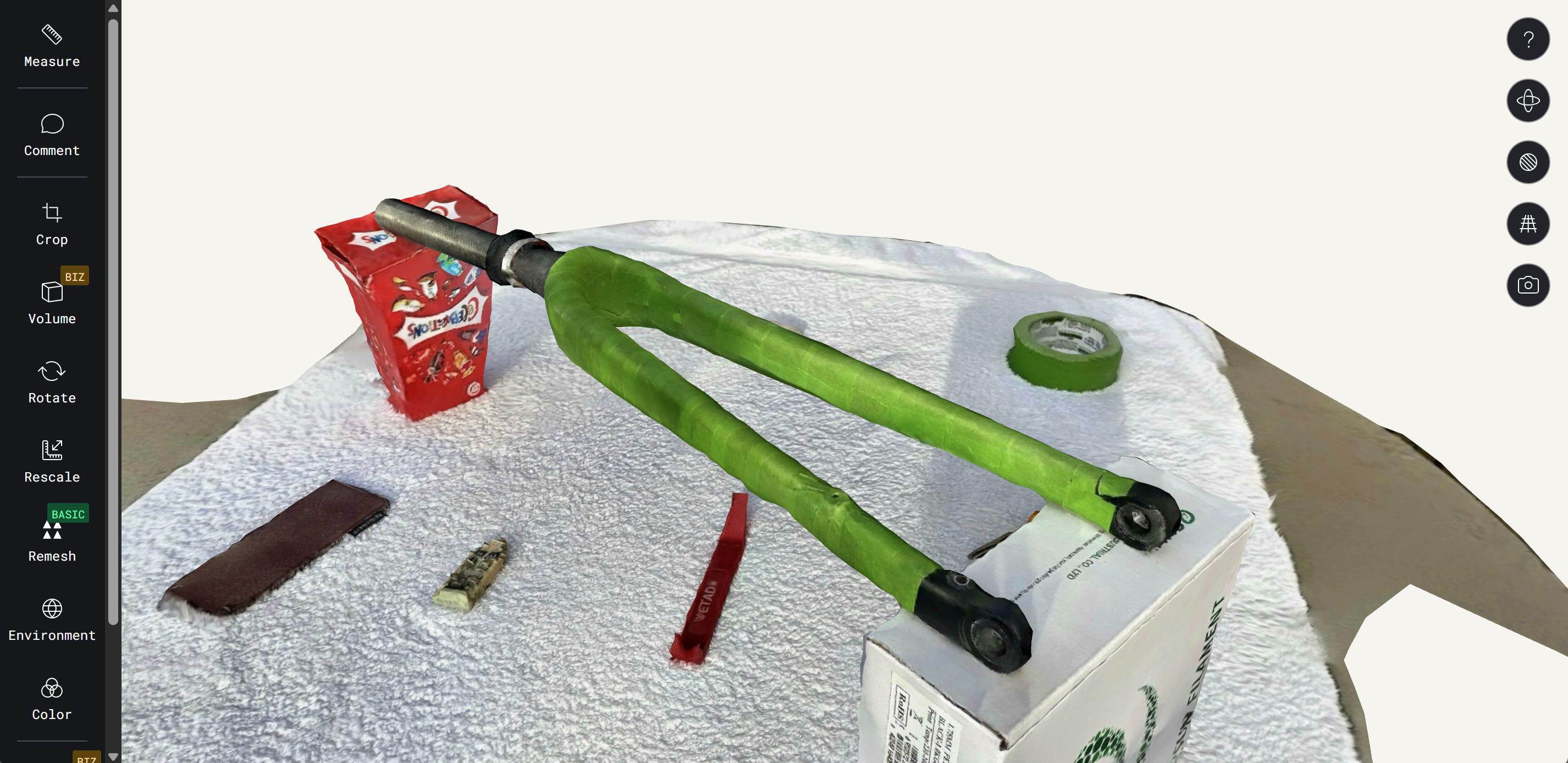
The coils had to sit inside the fork blades of a carbon fibre racing bike, and there was no access to a CMM, laser scanner, or any institutional tooling. The wheel profile was captured through physical measurement: callipers, radius gauges, manual section profiling. The fork geometry was captured via photogrammetry, fiducial tape applied to key surface features, 300+ images captured from all angles with reference items for scale and depth. The matte black carbon with natural contours was extremely difficult to capture on the equipment we had. We ended up wrapping the fork in green tape to create a cleaner profile for Polycam, and there aren't many bright days in a Scottish winter to help with lighting. The STL mesh was imported into Fusion 360, learned specifically for this workflow, and used as reference geometry to model the shroud. The mating face was cut directly from the photogrammetry data so the shroud sat seamless against the fork surface. The design included an electromagnet cutout, wiring channels, and an integrated air duct that forces air over the coil during riding, improving cooling and runtime by over 30% before overheating and meaning we could run more amps and extract more power. The duct was a major performance gain and completely discreet when the shroud was installed. Printed in carbon-fibre-reinforced filament for structural and thermal performance, with PETG used where vibration resistance was needed to prevent failure under hard riding. Production fit on the carbon components in two iterations.
.jpeg)
.jpeg)
.jpeg)
.jpeg)
.jpeg)
The system was built from first concept to rideable prototype — sole technical lead across the full development, with a close friend and fellow mechanical engineer joining during the build and manufacturing phase. Managed the client relationship with GCN throughout: regular calls, progress alignment, and producing build documentation and media content for their team. Three prototyping stages: a small-scale proof of concept for motor control viability, a full-scale wheel-in-fork development prototype for electronic and shroud iteration, then final integration into the complete bike. Controlled testing delivered 16W continuous and 23W peak. The resulting GCN video exceeded 500,000 views within 48 hours — described as the fastest-performing video in GCN's history at the time — and has since surpassed one million views. It prompted a second collaboration with Be Amazed (13 million subscribers) and renewed engagement with the UCI on motor doping detection methods.
End-to-end ownership of a complex electromechanical system across magnetics, mechanical design, firmware, thermal management, and stakeholder delivery. The embedded control system was written from scratch on an ESP32-S3: position-synchronised coil firing via hall sensor edge detection with configurable angular offset and firing window, dual-channel closed-loop PI current control at 1kHz, 20kHz PWM at 10-bit resolution, regular and turbo operating modes with independently configurable current limits, overtemperature protection wired to a calibrated thermistor LUT, and full run telemetry logging to non-volatile flash. Before the build, I travelled to Budapest to interview Stefano Varjas — the only publicly known motor doping mechanic — alongside Chris Marshall-Bell and Nicholas Raudenski (UCI head of anti-motor-doping), using those conversations to directly inform the system design. The project required moving fluently between FEA simulation, genetic algorithm development, CAD across two platforms, rapid prototyping in multiple materials, and managing a media partnership with hard deadlines — designed, built, and delivered on a £500 budget with domestic tools.