Autonomous Sphere Robot
Fully enclosed autonomous navigation
Fully enclosed autonomous navigation
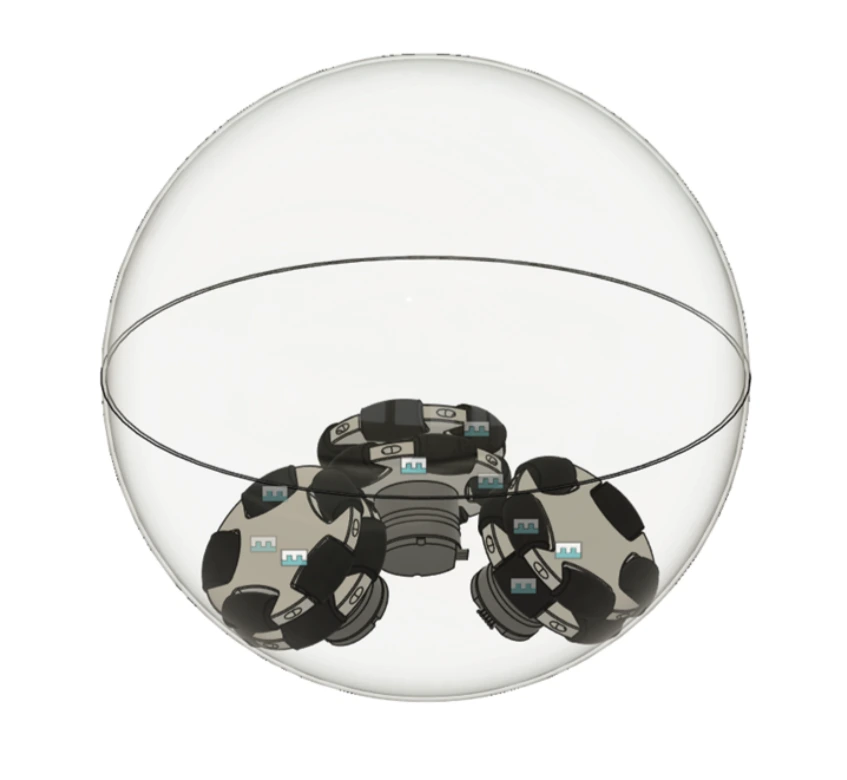
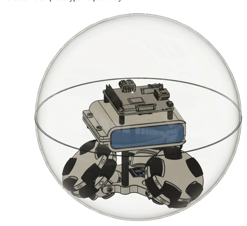
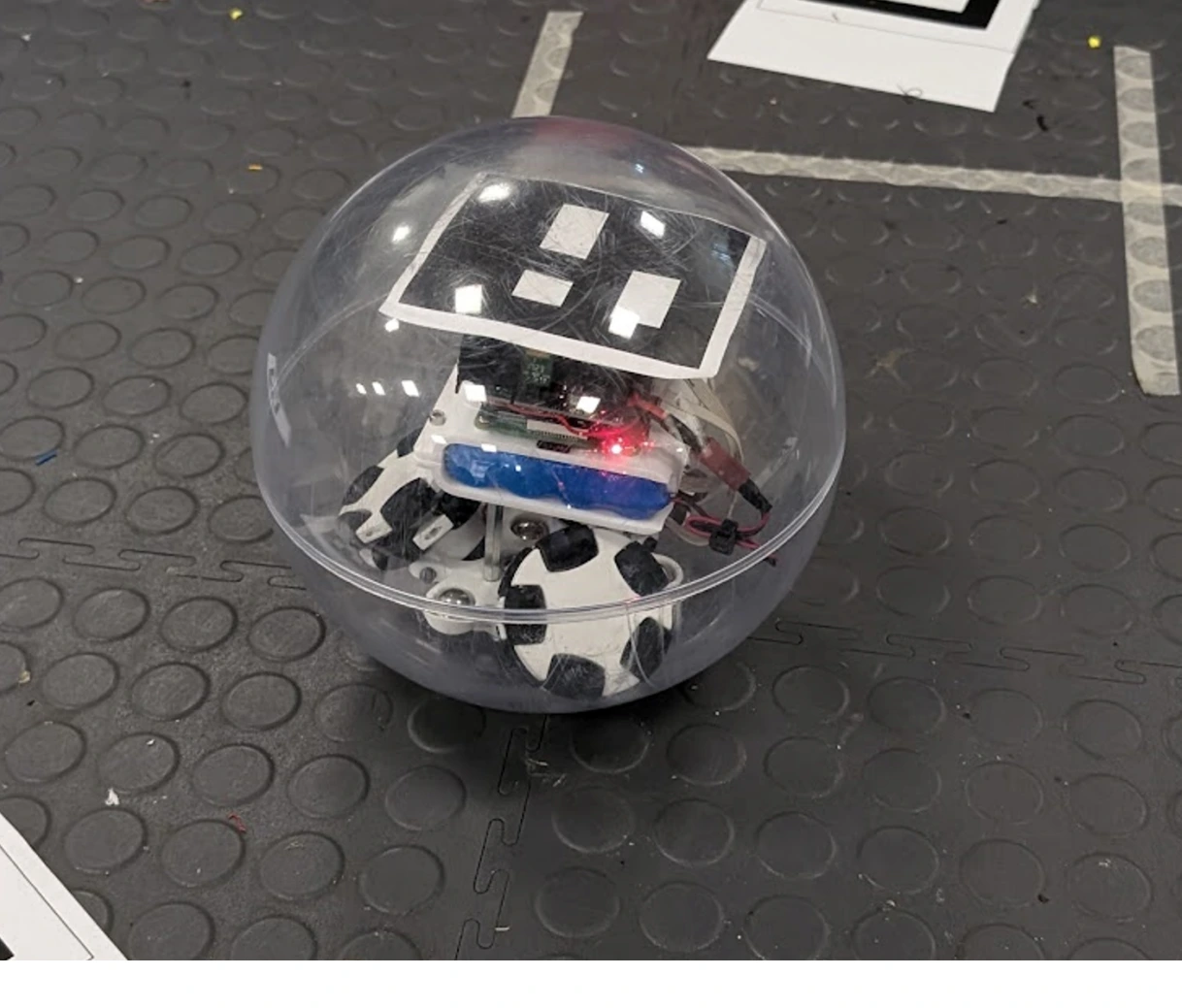
A team of four was tasked with building a spherical robot capable of autonomously navigating an arena using computer vision, enclosed entirely within a 200mm acrylic sphere. I was the mechanical design lead. The constraint that applied to everything: no pre-assembled components from external suppliers. Every omniwheel, bracket, and mount had to be designed and built from scratch. No published research existed on using a Kiwi drive inside a sphere, so the geometry, the kinematics, and the physical viability of the concept were entirely untested going in.
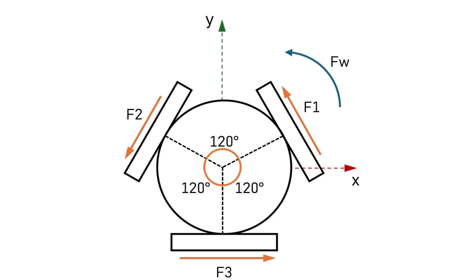
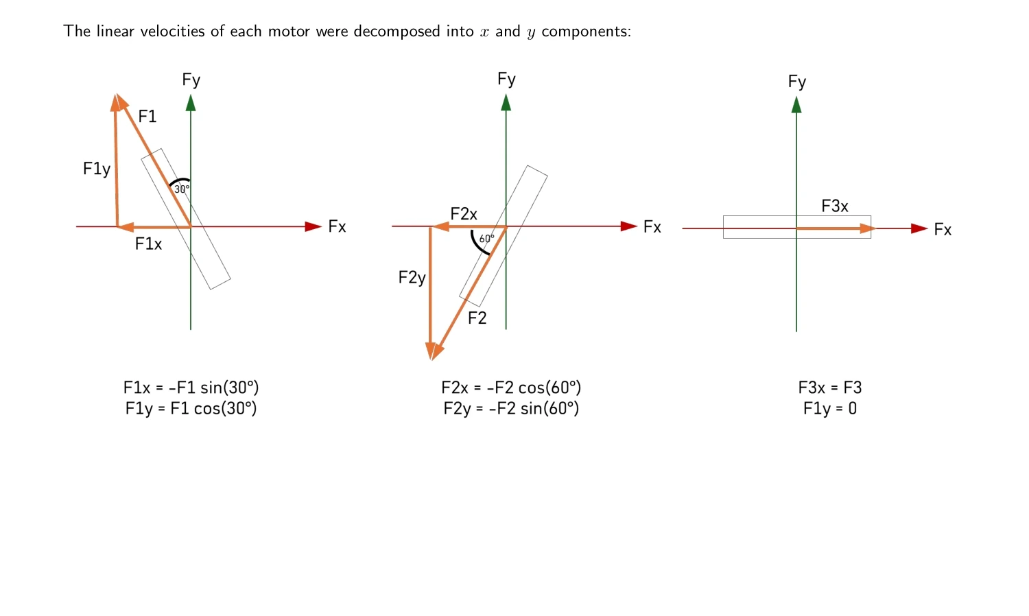
The first task was deriving the motor speed equations. A Kiwi drive uses three omniwheels at 120 degrees to each other, and each motor needs a specific speed to produce any given Cartesian velocity. The derivation uses force decomposition to express x, y and rotational movement as a matrix, which is then inverted to yield individual motor speed coefficients. A widely referenced tutorial covering this had the matrix wrong. That was caught, corrected in MATLAB, and the right equations were handed to the Robot Control subsystem as the basis for their Simulink model. Using a Cartesian coordinate system throughout meant the robot never needed to rotate on the spot to change direction. The holonomic drive handles that geometrically.
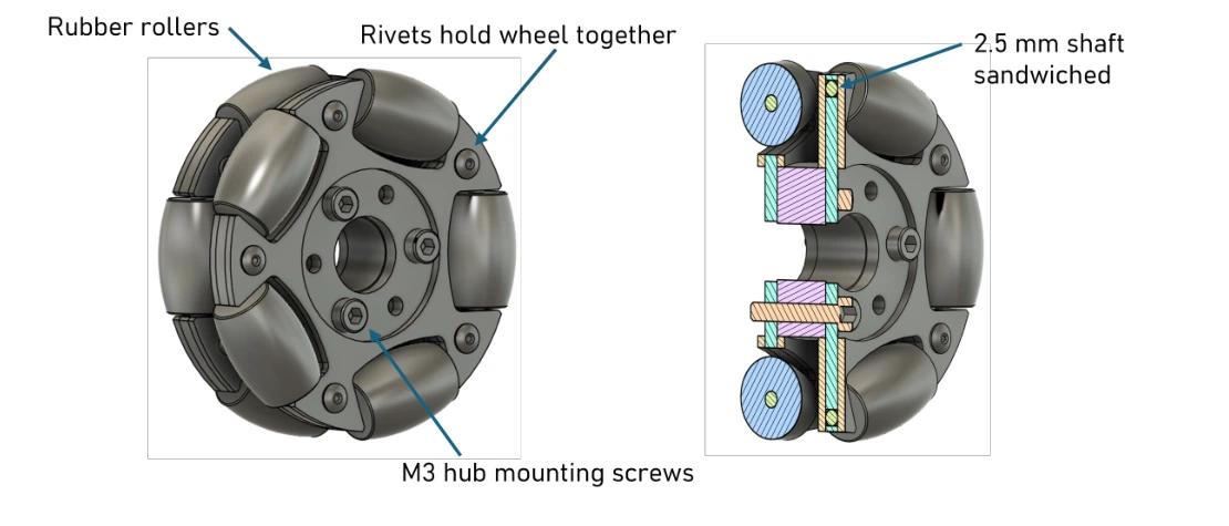
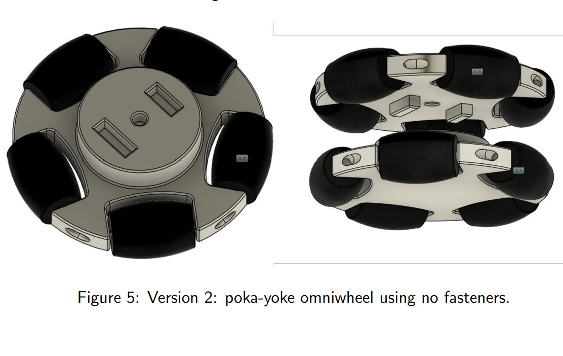
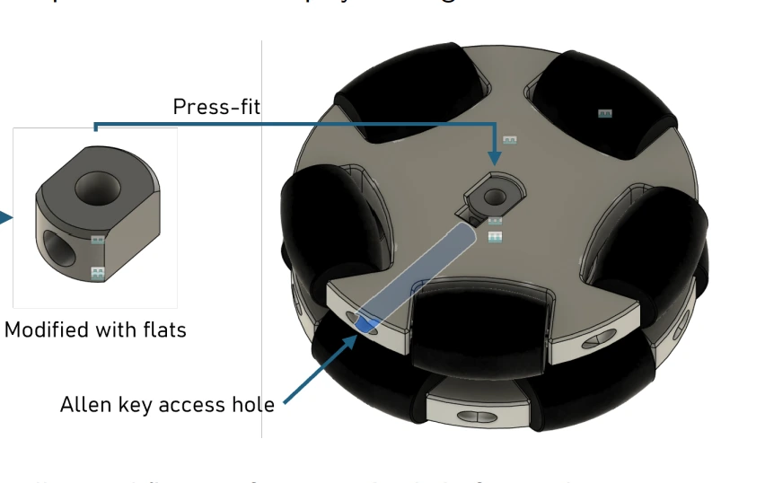
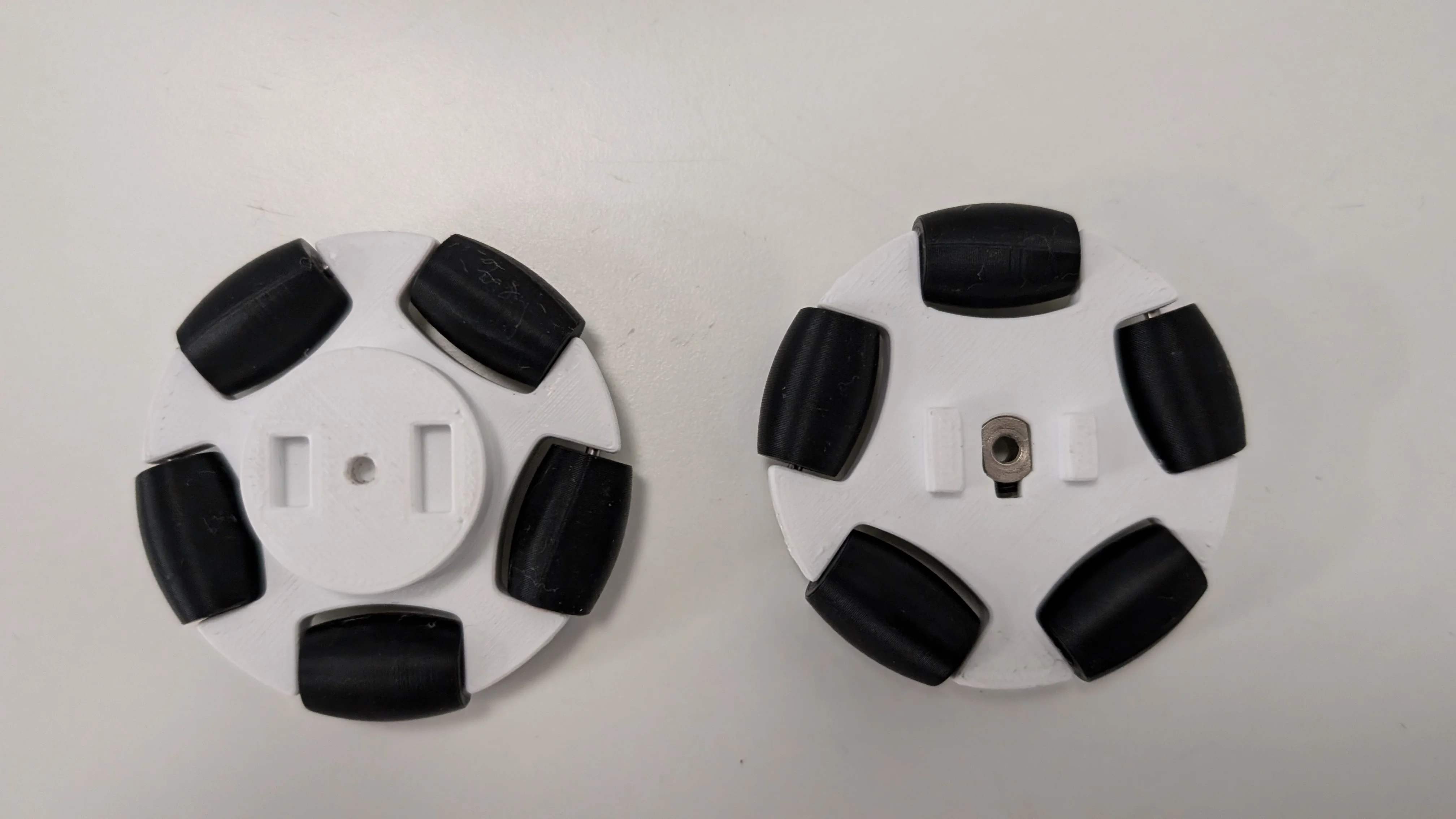
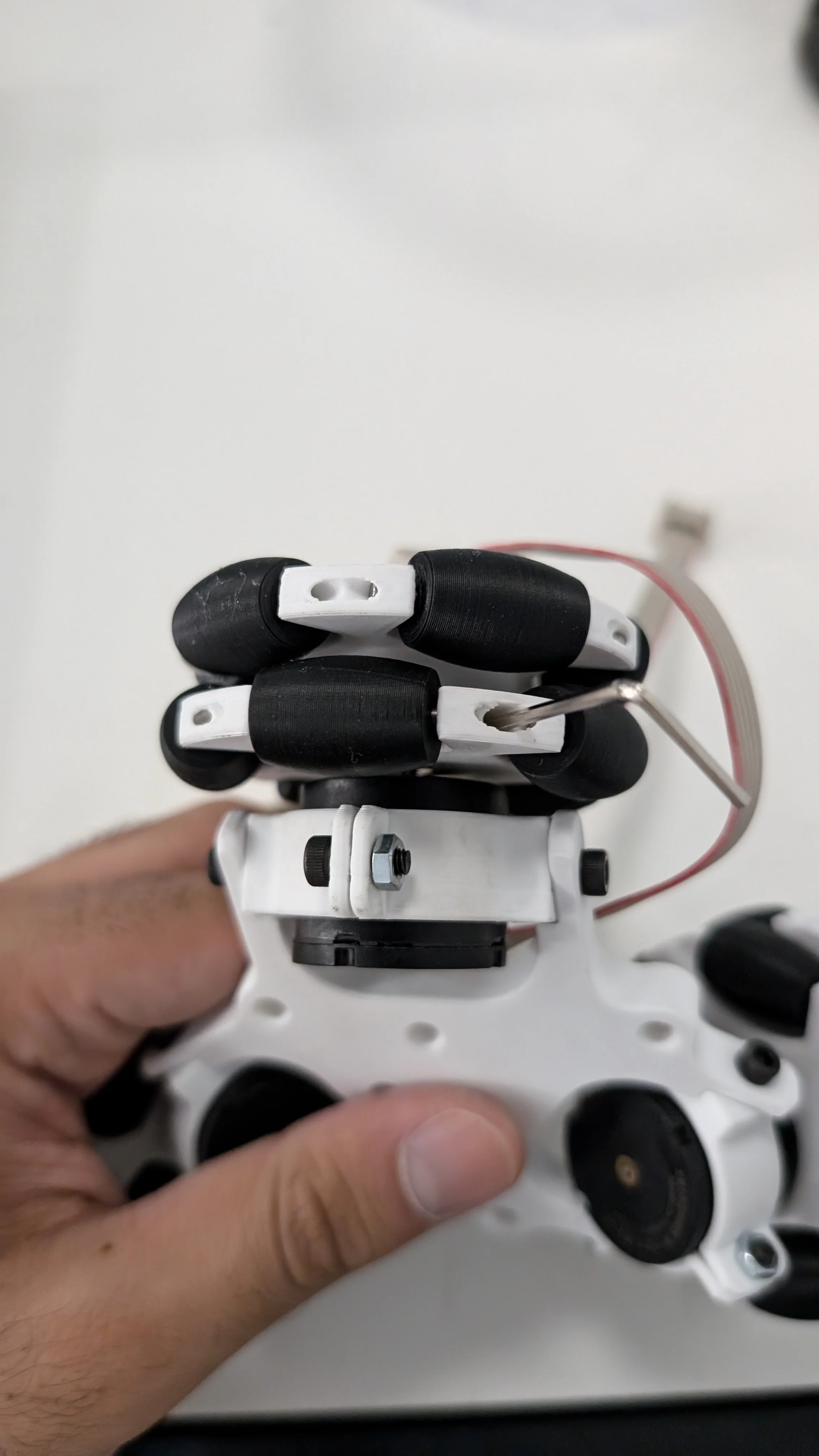
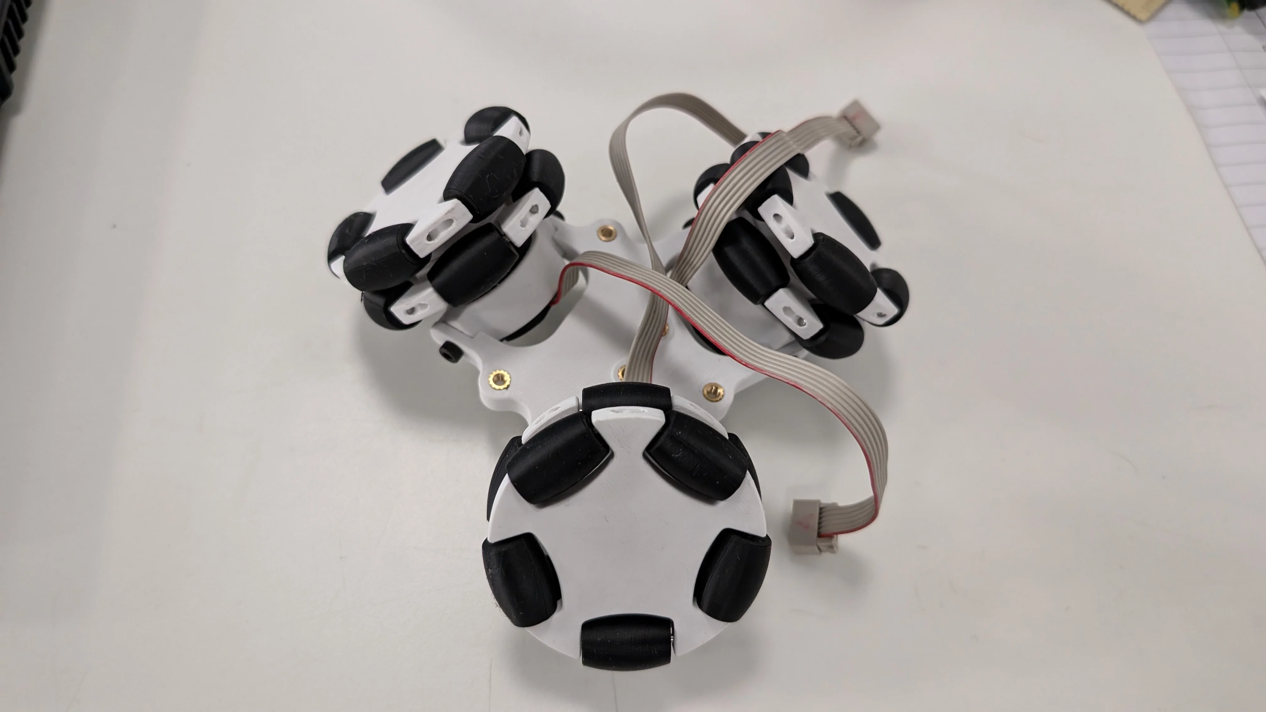
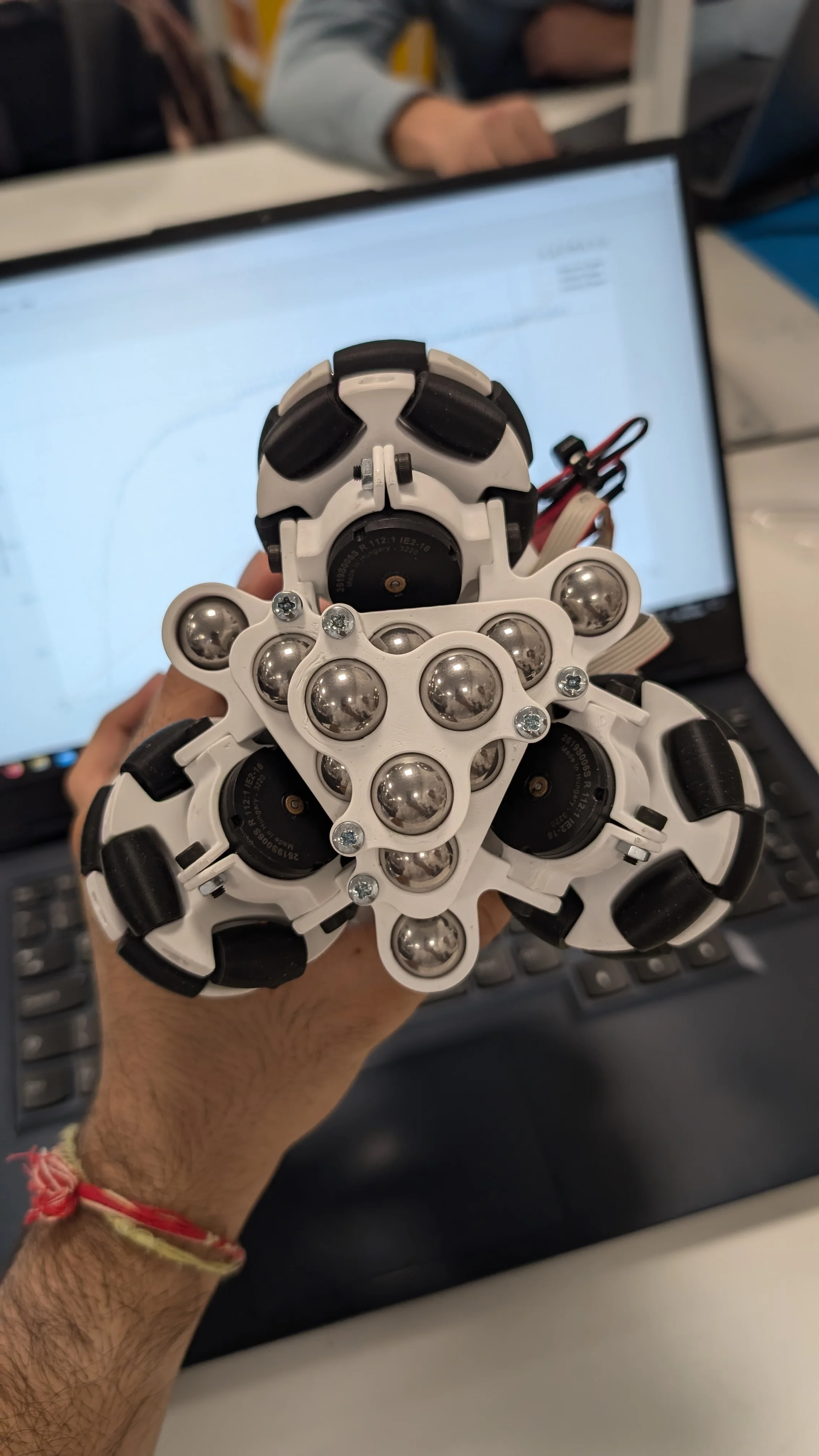
The project specification ruled out buying any pre-assembled components, so the omniwheels had to be built from scratch. The first version used M3 fasteners to hold the two halves together. It worked but the additional hardware increased rotational inertia and wasted material, so the approach was dropped. The second version replaced the fasteners with a poka-yoke key that interference-fit the two cores together, locking the rollers in the correct orientation without any hardware. The third version solved the shaft attachment problem. Grub screws into printed plastic strip the thread, so standard 3mm shaft collars were purchased, modified by filing flats parallel to the grub screw, and press-fit into the omniwheel core. An Allen key through an access hole tightens the collar onto the motor shaft without any disassembly. TPE-83A was chosen for the rollers because its lower hardness increases the contact patch against the sphere's interior, giving adequate grip against the smooth acrylic.
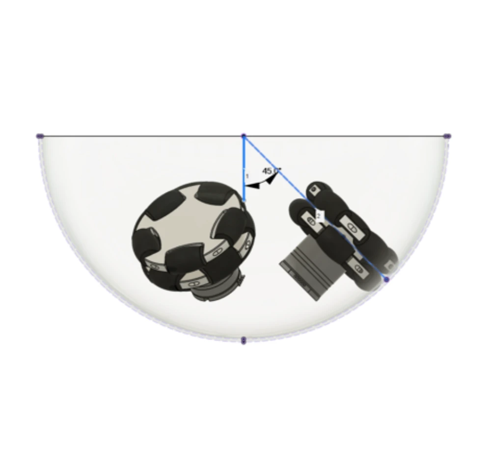
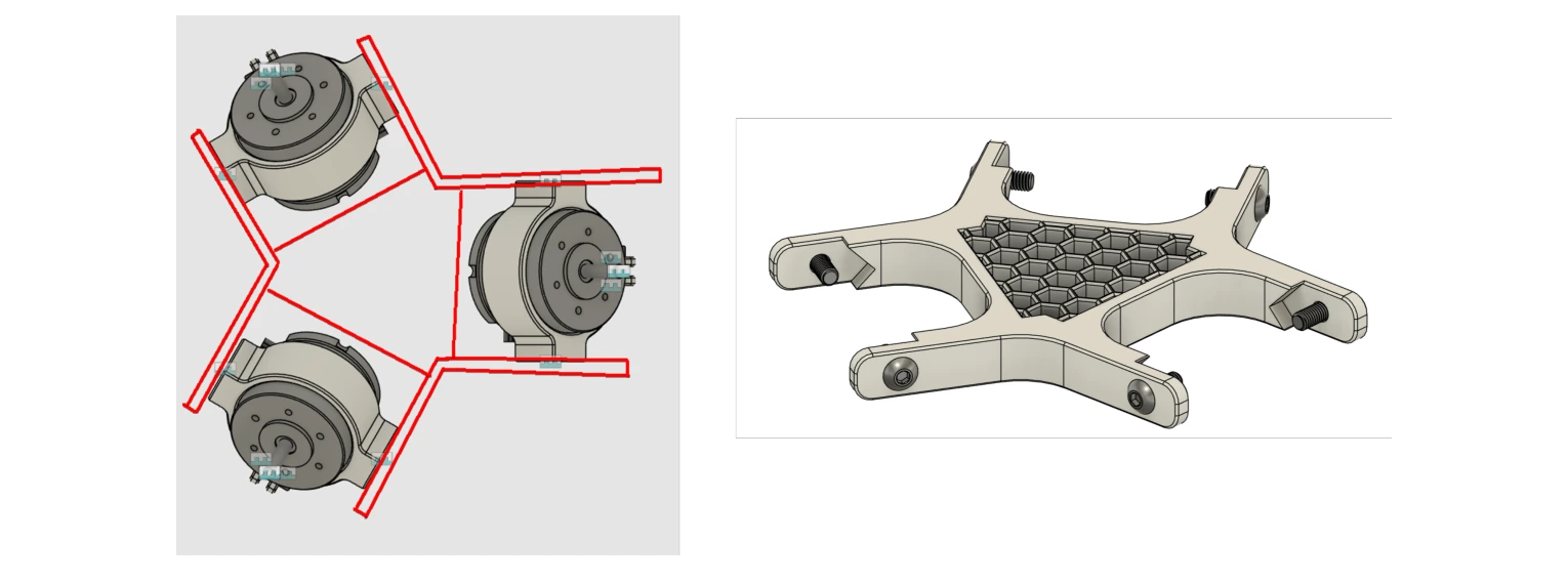
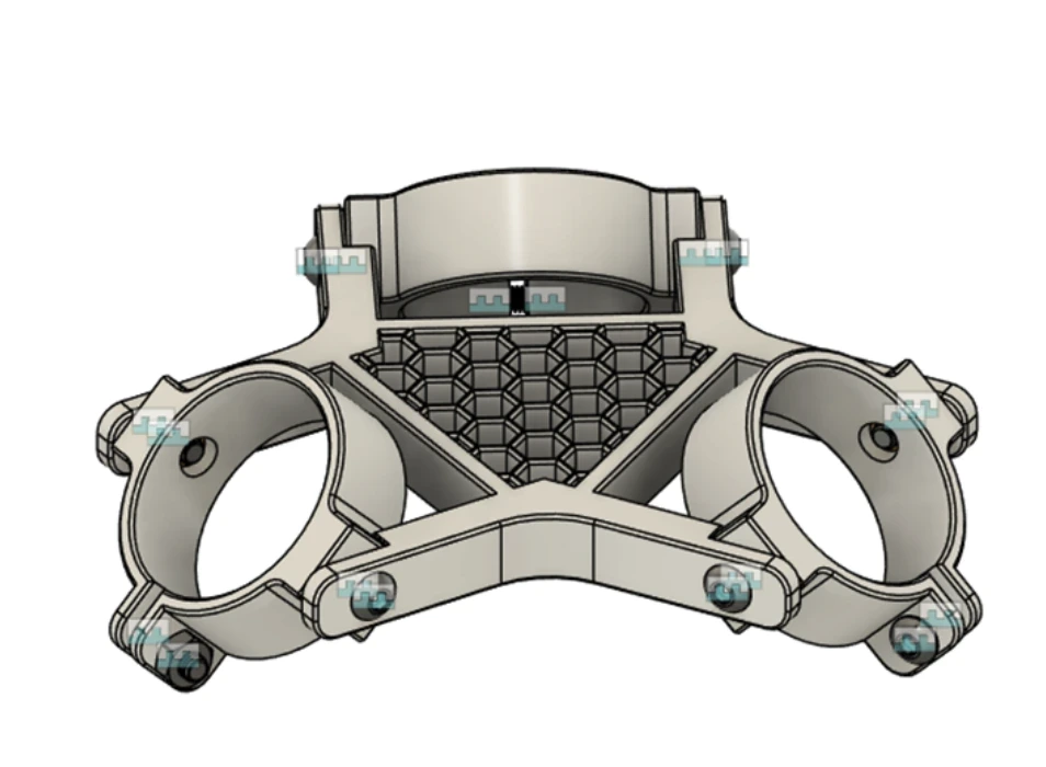
The omniwheels needed to sit tangential to the sphere's interior at exactly 45 degrees from centre for the drive geometry to hold. The mounting bracket clamps around each Faulhaber motor using an M3 screw and nut, with a square indexing feature that sets the angle without any measuring. Heat-set inserts replaced all plastic-threaded connections on load-bearing joints, preventing thread degradation over repeated assembly. The bracket was designed to print in under 30 minutes and allow individual motor removal without touching anything else. The progression from a sketch in MS Paint to a printed bracket to a fully assembled drive unit took one day.
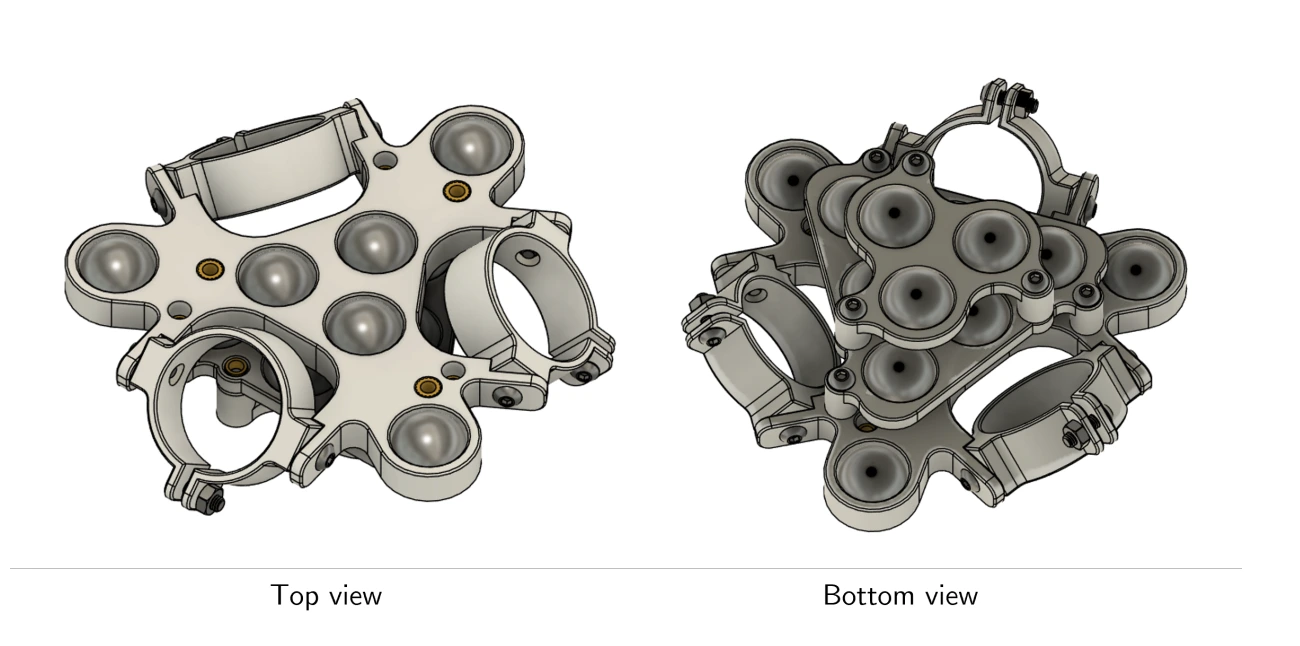
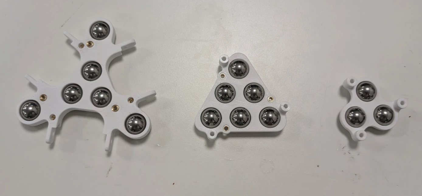
The first motion tests showed the robot veering off course and oscillating along its travel axis. The causes were compounding. The centre of gravity was off-axis because a temporary breadboard was sitting asymmetrically on top. The motors were running open-loop with no speed matching between them. And terrain vibrations were amplifying small imbalances in the internal hardware. Switching to closed-loop PI speed control through the Raspberry Pi brought the oscillations down significantly. The robot still fell over on aggressive direction changes because the battery mass was sitting too high above the motor contact plane. The fix was a set of printed trays press-fit with 18 solid 15mm steel balls, bolted to the undercarriage of the bracket. Moving that mass below the motor plane stabilised straight-line travel.
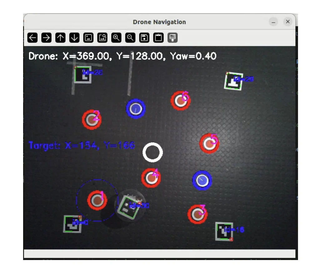
The robot had no way to be detected by the overhead camera until a visual marker was added. An ArUco code was fixed to a 3D printed plate screwed onto the electronics stack, positioned so it remained visible from directly above at all times. The corners of the plate were chamfered to prevent them catching on the seam of the sphere when it was closed. With the marker in place, the computer vision algorithm could track the robot's position and yaw angle in real time, feeding that data back through MQTT so the robot could navigate autonomously to marked points in the arena.
The robot met all 15 subsystem design specification requirements. It navigated autonomously, maintained heading through closed-loop yaw control, and delivered genuine omnidirectional motion without rotating on the spot. The main limitation was that active roll and pitch control through the IMU was not fully integrated, causing instability on step-input direction changes. That was a software constraint, not a mechanical one. A 200mm sphere does not leave much room for error in geometry, mass distribution or electronics layout. Every dimension that mattered was reasoned from a constraint and tested against it.
Full mechanical design ownership across a four-week build, as part of a cross-disciplinary team of four. No off-the-shelf components. Every part was reasoned from a constraint: the poka-yoke keys, the shaft collar modification, the indexing features, the heat-set inserts, the steel ball ballast. The problem-solving arc from open-loop oscillation through to a stable, tracking robot shows how physical design decisions and system behaviour are connected in a real mechatronics build.